Thorp Air Command - T18.net

Supporting Owners, Builders and Pilots of the Thorp T-18 and its variants.
It is currently Sat Apr 27, 2024 6:46 pm

All times are UTC - 6 hours [ DST ]


Post new topic Reply to topic  [ 6 posts ] 
Author Message
Steve H
 Post subject: Inspection Hole Location
PostPosted: Mon Feb 12, 2024 8:21 pm 
Newbie
Newbie

Joined: Mon Jul 04, 2022 9:45 am
Posts: 13
My plane is N80LC, an S-18. I've been it's caretaker for about 18 months. It sat for many years and became home for a LOT of mice. I cleaned up the inside of the fuselage bottom skin, removing some surface corrosion...enough to really make me want to look at the wings.

So, I need to inspect the inside of the wings, but the only inspection holes are located at the aileron bellcrank. I have inspected the 3 inner bays through these and the lightening hole in the inboard rib. There is no corrosion in these bays.

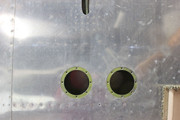
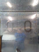
The photo is the outboard bottom of the wing, showing the outer 2 bays. I have taped inspection hole doubler rings to the skin where I want to install the inspection holes, centered in the bay forward/aft between the spars and left/right between the ribs. I am orienting them parallel to the ribs to have the greatest access possible to clean up if any surface corrosion is found. I will also to duplicate this pattern in each bay in the center section. All the screws/rivets will be dimpled.

Our EAA chapter technical counselor says the location/size of the holes and rivet pattern/spacing are OK. However, I would appreciate any comments you have concerning this. I suggested a 2 row staggered rivet pattern on the doubler ring, but he didn't think that was necessary.

Image

Thanks!
Steve H
2OK7
Newcastle, OK

_________________
Steve H
N80LC S-18
SN 38
2OK7


Top
 Profile  
 
James Grahn
PostPosted: Tue Feb 13, 2024 12:19 am 
Hero Member
Hero Member

Joined: Sat Oct 24, 2009 7:16 pm
Posts: 1435
Images: 0
Location: USA
Have you looked at AC43-13? It is a huge wealth of information. This will be addressed in this publication.
Cubes


Top
 Profile Personal album  
 
Steve H
PostPosted: Tue Feb 13, 2024 9:07 am 
Newbie
Newbie

Joined: Mon Jul 04, 2022 9:45 am
Posts: 13
Hi Cubes.

Yes, I have studied AC43. There are no references to installing inspection plates that I can find.

4-58. REPAIR METHODS AND PRECAUTIONS FOR ALUMINUM STRUCTURE, para. e., references making flush patches in accordance with Figure 4-16. The patch would be installed on the bottom surface the skin and a filler riveted onto the patch flush with the skin.

FIGURE 4-16. Typical repairs of stressed sheet metal coverings.

In the right side patch example of the upper drawing in figure 4-16, the doubler ring for the inspection plate assembly would the stiffener to back up the seam of the patch. The inspection plate would the patch plate. However, the inspection plate will not overlap the skin, just the doubler. The doubler ring, inspection plate, rivet size and spacing are to match the surrounding skin pattern. The pattern of the inspection plate screws would have to match the rivet pattern, and screws would have be structural to be used in place of rivets.

It's not readily obvious if the stiffener has a flange.

The bottom drawing in figure 4-16, referencing the patch A to D, over a hole in the skin, really doesn't apply since there is no doubler involved.

The installation of circular patches are don't seem to apply to this.

The video showing installing the Piper inspection plate AD shows installation of the doubler ring (which is not flanged) with single row of rivets. However it isn't installed in the middle of the span of the wing.

_________________
Steve H
N80LC S-18
SN 38
2OK7


Top
 Profile  
 
Rv3maker
PostPosted: Tue Feb 13, 2024 11:37 am 
Newbie
Newbie

Joined: Sun Oct 15, 2023 9:06 am
Posts: 26
Images: 0
Location: Halstead, KS (Wichita area)
Do you have the S-18 drawings? Assuming you do, I would consider just making them the same as depicted on drawing 300L, parts 300-3 and 300-4 and locating them where you would like.

Rob


Top
 Profile Personal album  
 
Steve H
PostPosted: Tue Feb 13, 2024 6:40 pm 
Newbie
Newbie

Joined: Mon Jul 04, 2022 9:45 am
Posts: 13
Hi Rob.

I do have the plans so I'll compare them with what I have.

Thanks.

_________________
Steve H
N80LC S-18
SN 38
2OK7


Top
 Profile  
 
Steve H
PostPosted: Wed Feb 14, 2024 4:26 pm 
Newbie
Newbie

Joined: Mon Jul 04, 2022 9:45 am
Posts: 13
I looked at the plans. I don't want to use the round inspection hole for 2 reasons: I would have to make one cut in the doubler ring to get it inside the wing, and the hole would be to small to work through.

I haven't liked putting the inspection hole in the middle of the bay from the start. After some measuring with my arm through the doubler ring, I figured out it didn't need to be in the middle. Also, the length of the hole was longer than necessary.

So, here's the new location, with a 1 1/2" shorter opening...3 1/2" x 5 1/2". This is basicly the same installation as the 4 inch inspection holes for the aileron bellcrank. I can move it a little closer to the front spar. You'll need to click on the photo to see the black marker showing the location.

Image

Image

Comments?

_________________
Steve H
N80LC S-18
SN 38
2OK7


Top
 Profile  
 
Display posts from previous:  Sort by  
Post new topic Reply to topic  [ 6 posts ] 

All times are UTC - 6 hours [ DST ]


Who is online

Users browsing this forum: No registered users and 9 guests


You cannot post new topics in this forum
You cannot reply to topics in this forum
You cannot edit your posts in this forum
You cannot delete your posts in this forum
You cannot post attachments in this forum

Search for:
Jump to:  

[ Time : 0.303s | 12 Queries | GZIP : On ]