Thorp Air Command - T18.net

Supporting Owners, Builders and Pilots of the Thorp T-18 and its variants.
It is currently Tue Jul 16, 2024 12:21 am

All times are UTC - 6 hours [ DST ]


Post new topic Reply to topic  [ 9 posts ] 
Author Message
PapaGolf
PostPosted: Wed Feb 07, 2024 12:51 am 
Newbie
Newbie

Joined: Fri Oct 02, 2020 5:59 pm
Posts: 5
As Bob Highley suggested in the FB group, I am finally starting a project thread here on .NET! I have been lurking this forum and the FB group for a while now but let me introduce myself. I'm Pete Geraci and I've been a mechanic for 25 years, starting in the Air Force, a few years at a GA flight school and then corporate jets for the last 18 where I've mostly specialized in avionics. I earned my private certificate in 2005 and have flown when I can although not nearly as much as I would like! That said, 2020 I was ready to start a father/sons project building an RV-14(boo I know!). Like many people, COVID changed a few plans and I decided that might have been a bad time for a major project. Talking with one of my friends at work, he told me the tale of a Thorp, how he came to own it, what his plans were, and how life events had taken his ability to really devote the time to it.

So, What started as helping a friend shed the cost of storing it, ended up with it occupying my garage for the last 2 years. As best as I can understand, This airframe was build by James Dewberry of Alabama and received its first CofA in 1972. According to the dataplate, it first flew with an O-290 and spent more time getting modified than flown. According to the airframe log it took nearly 21 years, 1993, to reach its first 40 hours! It then flew quite a bit for a while but was disassembled for storage in January of 2002 with 256 hours. The logbook is quiet for 11 years when suddenly it was fitted with a Lycoming O-360, went back to phase 1 for a few hours, and the last airframe logbook entry is the end of March 2012, when at 261.3 hours, it was returned to phase 2.

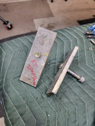
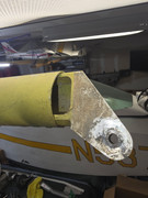
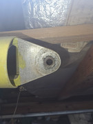
The owner at the time had trouble with ground handling and ran off the side of a taxi way (I'll go into my theory on that another day, no spoilers FB!). June of 2012, he removed the damaged Hartzell CS prop/governor, dialed the crank(.002), and installed a Sterba FP wooden propeller.

My friend traded his Cessna 152 for this, looking forward to the "Thorp Experience"! Unfortunately, a fuel leak developed in the custom built fiberglass fuel tank. He purchased the plans at that time with the intent of fabricating the fuel tank as drawn to install it and quickly discovered that the original builder had gone off the map with a custom tank, mounts, firewall supports, a set of modified Cessna rudder pedals and brake cylinders. The fiberglass tank was also smaller (I think 15 gallons), allowing for a full depth center avionics stack after the panel was relocated aft approximately 5 inches. So what started as going back to a plans built tank has tsunami'ed.

I was initially asked to evaluate it, see if it was even worth saving. The sad reality is, if the guys working for me weren't cheap, it would easily be beyond economical repair. For that fact, it would probably be easier and cheaper to buy the kit from Cubes and build! But, it landed in the lap of a nostalgic coot that has a knack for breathing new life into old stuff.

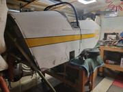
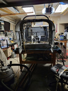
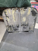
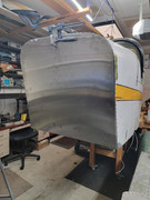
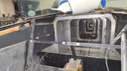
The tach, covered in dust sitting in a box of radios and gauges, reads 270.3 hours. The wings hang in racks from my garage ceiling, the tail feathers on the back wall. The engine found my homemade stand and the fuselage is casually hanging off of both ends of EAA 1000 inspired workbenches. A care package from Cubes showed up not so long ago with a new firewall and some misc. parts. So the question is, how good is an avionics guy at sheet metal!
Image

Image

Image


Top
 Profile  
 
PapaGolf
PostPosted: Wed Feb 07, 2024 1:18 am 
Newbie
Newbie

Joined: Fri Oct 02, 2020 5:59 pm
Posts: 5
The thread that got me started was things I found that were not in the drawings and I noticed were different from other T-18's out there. The first clue was the internal horizontal stabilizer balance weight. as drawn, is straight with the weight hanging in between the arms. Mine, has spacers where the weight should be, the weight hanging from the arms, and then the arms themselves are bent and reinforced. Looking at the current travel of the stab, the arms barely clear the upper skin leading me to believe this was modified to eliminate contact. The red markings on the angles are similar to others observed in the airframe so it would appear this was done at build.
Image

Image

The seat supports seem to be correctly located but the backs are extremely thin. The control sticks were bent and welded to move the grip approximately 4.5 inches aft of center as opposed to the straight sticks I've seen in most cockpit pictures. Shown is the removable copilots stick.
Image

I also found shims nearly 3/8's thick that moved the wing aft. I haven't found any spacers for the aft spar fittings but according to some measurements I took yesterday, I would have to have them to mate the wing with the main spar shims installed.

Image

Additionally, the instrument panel was moved approximately 4.5-5 inches aft which Bob Highley told me was a pretty common mod. This one however, had a full IFR stack with vacuum gyros and the most recent weighing showed 1363lbs @ 63.24. My theory is once a modern American and a sack of pilot stuff was thrown in the back that it may have created an aft CG condition. Locating the wing aft may have offset the flight characteristics a bit but I was curious how close I am to guessing an aft CG loading could make ground handling a little sporty. (I have no tailwheel time BTW so feel free to correct me)

Has anyone else seen anything like this or have any carnal knowledge of this airframe? Thanks again! -Pete


Top
 Profile  
 
Hagle347
PostPosted: Wed Feb 07, 2024 11:09 am 
Sr. Member
Sr. Member
User avatar

Joined: Tue Oct 26, 2010 3:42 pm
Posts: 567
Images: 19
Location: USA
There are 2 items of concern on the 'bob weight'. The weight itself should be sandwiched between the angle stock. AND the part should be straight - not 'adjusted'. Both point to the collar on the stab being installed at the wrong angle. I've seen that on another Thorp I was involved with on a much smaller scale . The result of this mod will not allow you to get the full and proper angle of up and down horizontal stab movement . That also negatively affects aircraft handing.
- With regards to the front spar shims....were the rear spars shimmed as well?

Keep posting and asking questions - We'll get it correct!


Top
 Profile Personal album  
 
James Grahn
PostPosted: Wed Feb 07, 2024 12:03 pm 
Hero Member
Hero Member

Joined: Sat Oct 24, 2009 7:16 pm
Posts: 1448
Images: 0
Location: USA
I think it’s worth saving!!
But I would return it to plans configuration. I’m not an engineer, but I can tell you that unintended consequences often happen with even minor mods. Those are not minor mods!
Terry is right, the 510 might have been installed at the wrong angle. Not sure how to fix that.
I would move the wing back to the normal position. With a fixed pitch prop, you should be right in the sweet spot of the CG.
Cubes


Top
 Profile Personal album  
 
PapaGolf
PostPosted: Wed Feb 07, 2024 6:11 pm 
Newbie
Newbie

Joined: Fri Oct 02, 2020 5:59 pm
Posts: 5
I'll have to check the angle of the 510 arm, it may be what it is. I'm changing the trim to electric so once I get to re mating the stab I'll check the throws to make sure I'm getting good deflection. Hopefully it was remedy for an Oops that worked out. re orienting the 510 doesnt look like an easy thing to do but I'll address that when I get there.

I haven't found any shims for the aft spar but I measured the wing and compared it to the fuse and there would have to be something there to take up the slack. Hopefully that doesn't mess with the flap slot alignment but thats a future me problem for now!

I'm definitely going to try and get this as close to the plans as I can. The firewall change came into play once I realized the original fuel tank supports were installed several inches outboard and the number of holes punched in it would probably divert the fire into the fuel tank! Another oddity was the angle that held the fire wall to the lower structural brace was on top of the brace instead of the bottom where the fuel tank mounts were solely supported by the firewall and not riveted to the brace. Thankfully I was able to unbolt the brace and flip it with out having to remove and re-rivet the angle on.
Image

good news is initial fitting of the new one is going well! Image


Top
 Profile  
 
James Grahn
PostPosted: Thu Feb 08, 2024 12:49 am 
Hero Member
Hero Member

Joined: Sat Oct 24, 2009 7:16 pm
Posts: 1448
Images: 0
Location: USA
Awesome! You do quick work.
Cubes


Top
 Profile Personal album  
 
fytrplt
PostPosted: Thu Feb 08, 2024 10:17 am 
Hero Member
Hero Member
User avatar

Joined: Tue Oct 20, 2009 8:07 pm
Posts: 1145
Images: 2
Location: Lakeland, Florida, USA
A quick check of your stabilator and the placement of the 510-1 bracket may tell the tale. The 510 is to be installed 14 degrees 2 minutes slanted up from the horizontal axis of the stab. A not so uncommon mistake of the early builders was to install it at right angles to the stab. Many early builders were building ahead of John Thorp's final release of drawings. Several were being built in the Atlanta area and even had round fuselages. The fatal accident that resulted in the redesign of the horizontal tail was caused the bracket installation mistake and subsequent fix. The builder drilled out the rivets on 510-1 and correctly positioned it and redrilled the holes and re-riveted it. He essentially perforated the tube spar. A sharp pull up after a highspeed pass was all it took to fracture the spar. The spar doubler, redistributed bobweights, and the oh so important stainless steel straps on the tab were a result of this accident.

If you make your way to Sun 'n Fun this year, I would be glad to meet up with you and show you my finished plane and the one I have under construction. I am based in Lakeland Florida.

_________________
Bob Highley
N711SH
SN 835
KLAL


Top
 Profile Personal album  
 
Rv3maker
PostPosted: Sat May 11, 2024 10:55 am 
Newbie
Newbie

Joined: Sun Oct 15, 2023 9:06 am
Posts: 35
Images: 0
Location: Halstead, KS (Wichita area)
PapaGolf, how is it going? Any updates? Keep us posted!

I am going to start a project thread pretty soon myself . . . .let's keep each other in check!

Rob


Top
 Profile Personal album  
 
PapaGolf
PostPosted: Thu Jun 27, 2024 9:00 pm 
Newbie
Newbie

Joined: Fri Oct 02, 2020 5:59 pm
Posts: 5
RV3maker. Thanks for asking! Unfortunately my family and I were hit with a series of health issues that knocked down my ability to get the physical work done for a bit. Hopefully I’ll be able to pick up the rivet gun soon!

In the meantime just for an update, the vacuum system and original instrument panel have been donated to a local High Schools budding aviation program. Some shopping and horse trading has landed me with a 10” Dynon Skyview system with the engine monitor for the Lycoming that’s still awaiting overhaul. I also picked up an efis-d10a that will make a good standby instrument. It came with the autopilot servos, although I had no plans for an AP, they’re compatible with Skyview so I guess I’ll have an AP! A Stratus ES transponder will replace the King KT76 mode C unit to fit the ADS-B out requirement. I have a stratux unit I’ve used for ads-b in. I’m going to experiment and see if it will feed the Skyview. Worst case I’ll have the data on ForeFlight for now.

The only issue I have right now is what to do with the other stuff I have. I still have an ICom VHF radio, a Narco Mk12D with glide slope. And a KLN-89B IFR GPS. Oddly enough I’m considerings reusing them. I like the idea of having VOR/ILS and even though the Skyview has WAAS, the 89B is approach certified. I don’t have my instrument yet but I like the idea of being equipped in case I end up in the soup. I would eventually like to get a good navigator so I can fly a nav coupled approach but getting it flying and back through phase 1 is the priority.

Engine wise, the O-360 was prop struck, 300 beyond TBO, and hasn’t been run since 2012 as best I can tell. The Carb wasn’t drained so it needs an overhaul. The dual mag is obsolete and several hundred beyond its 500 hour. The ignition harness is shot as well. That said I’ve been considering going with an EFI/electronic ignition system. I’m not excited about flyefii or system32 though.

To that end, I’ve been bench testing a custom ECU with the goal of having a full sequential injection/ignition. The other two use a batch fire, wasted spark algorithm that leaves fuel sitting on the back of the intake valve and double fires every spark plug. The one that has an option for a redundant ecu apparently has a rather unnerving changeover if something happens. My sitting on the couch for 3 months design is based off the same FADEC that runs the Rolls Royce BR-710 engines on the G550s I take care of. Effectively two always on engine controls that take turns being in control monitored by a third that can vote one off the island if it starts acting stupid.

So that’s the latest! I’ve taken the downtime to do all of the brain work. Drawing schematics, acquiring parts, and rebuilding the typewriter written flight manual. It’s been a lot of work but since I can’t fly right now anyways, I might as well build!

I’ll keep an eye out for your project thread, always good to see what we’re all up to!


Top
 Profile  
 
Display posts from previous:  Sort by  
Post new topic Reply to topic  [ 9 posts ] 

All times are UTC - 6 hours [ DST ]


Who is online

Users browsing this forum: No registered users and 3 guests


You cannot post new topics in this forum
You cannot reply to topics in this forum
You cannot edit your posts in this forum
You cannot delete your posts in this forum
You cannot post attachments in this forum

Search for:
Jump to:  
cron

[ Time : 0.136s | 11 Queries | GZIP : On ]