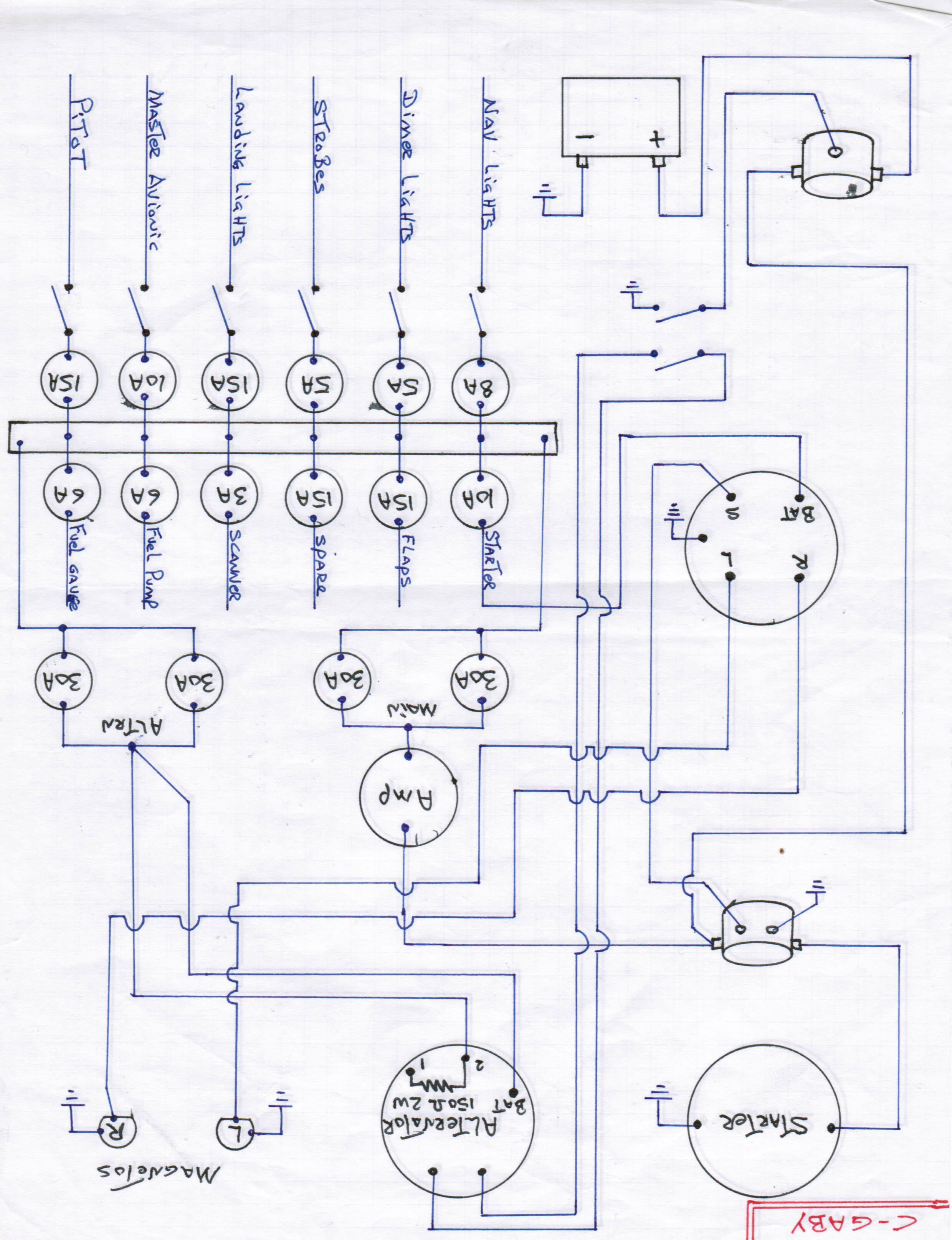
Well I spent the afternoon upside down under the panel and swapped out the two 30 amp breakers and replaced them with a single 60 amp (from ACS); unfortunately it made no difference at all; 0 output from the alternator.
I measured 12.6 volts at post #2 on my alternator

(there is another wiring diagram in my photo album if that helps)
with the master switch on (engine off), I also get 12.6 volts at post #1 (engine off). I studied the wiring diagram and am at a loss to explain why there is a resistor between post #1 and #2. None of the "experts" at the airfield knew what that was about either.
I disconnected the plug (GM wiring harness two plug white plastic connector) and measured 17 ohms between post #1 and #2.... that is contrary to what it APPEARS should be there (150 ohms)... is that the problem?....roasted resistor?
I am disheartened and just want this fixed...any ideas if I am on the right track.
ps;
"The only other thought I have that might (or might not) be helpful is that with many of the old Delco separate regulator circuits, the trouble indicator got positive at the panel, through the light bulb, to the alternator. If the bulb burned out, the alternator would not charge, and some replaced it with a resistor. I think with an internal regulator that would be the wire closest to the fat wire, the other would go to +batt. The "modified" blue wires are a mystery - probably to shut it down, as you suggested."
the alternator failed light works!


